As interest in colonizing the Moon increases, developing a sustainable method of transporting equipment and resources to and from the lunar surface will be necessary. LANDER's approach to this problem is a system that uses one thruster capable of vectoring thrust to control vehicle attitude and perform propulsive landings with minimal fuel use. However, key to the design challenge is creating a suitable test environment for such a system that can simulate variables, such as lunar gravity and a lack of atmosphere. Project LANDER endeavored to provide a potential solution by designing a complex simulation utilizing live data. Due to an abbreviated timetable and low-quality components, LANDER did not meet all of its requirements for the Thrust Vector Control Test and Operational Demonstration. However, while LANDER was a proof–of-concept system, the team hopes to lay the foundation for future development in this area.
The experimental thrust curve shows that the four load cells managed to match the thrust curve for the Estes F15 within 6.2 Newton Seconds or 13.2%. These results are very impressive given the quality load cell and vehicle manufacturing from AXFAB.
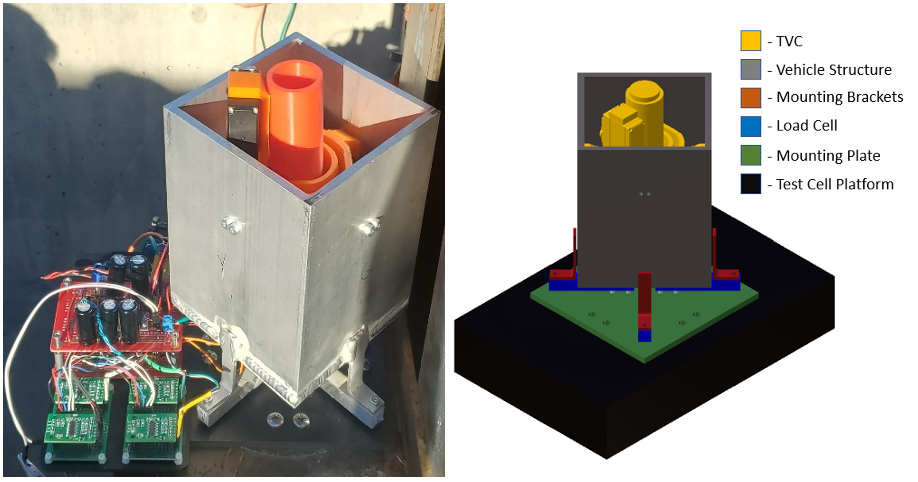
As shown in the figure to the right, the TVC is the yellow assembly mounted inside of the rectangular vehicle. The red mounting brackets of the vehicle are screwed into the blue load cells. The load cells are bolted to the green mounting plate, which connects the vehicle assembly to the black test stand.
As shown in the figure to the right, the TVC is the yellow assembly mounted inside of the rectangular vehicle. The red mounting brackets of the vehicle are screwed into the blue load cells. The load cells are bolted to the green mounting plate, which connects the vehicle assembly to the black test stand.
As shown in the figure to the right, the TVC is the yellow assembly mounted inside of the rectangular vehicle. The red mounting brackets of the vehicle are screwed into the blue load cells. The load cells are bolted to the green mounting plate, which connects the vehicle assembly to the black test stand.
LANDER compiled all of the work and findings from the two semesters spend in capstone into a single document.