As interest in colonizing the Moon increases, developing a sustainable method of transporting equipment and resources to and from the lunar surface will be necessary. LANDER's approach to this problem is a system that uses one thruster capable of vectoring thrust to control vehicle attitude and perform propulsive landings with minimal fuel use. However, key to the design challenge is creating a suitable test environment for such a system that can simulate variables, such as lunar gravity and a lack of atmosphere. Project LANDER endeavored to provide a potential solution by designing a complex simulation utilizing live data. Due to an abbreviated timetable and low-quality components, LANDER did not meet all of its requirements for the Thrust Vector Control Test and Operational Demonstration. However, while LANDER was a proof–of-concept system, the team hopes to lay the foundation for future development in this area.
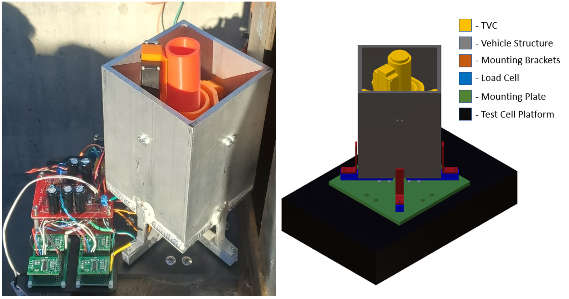
The fully assembled system and the CAD of the system can be seen on the figure to the right. LANDER consists of 5 subsystems, Control Software, Avionics, Control Mechanisms, Structure, and Test Stand. These subsysems all come together to produce a test stand capable of simulating a vehicle landing on the lunar surface. The test stand involves a complex hardware in the loop computer simulation running on a microcontroller.
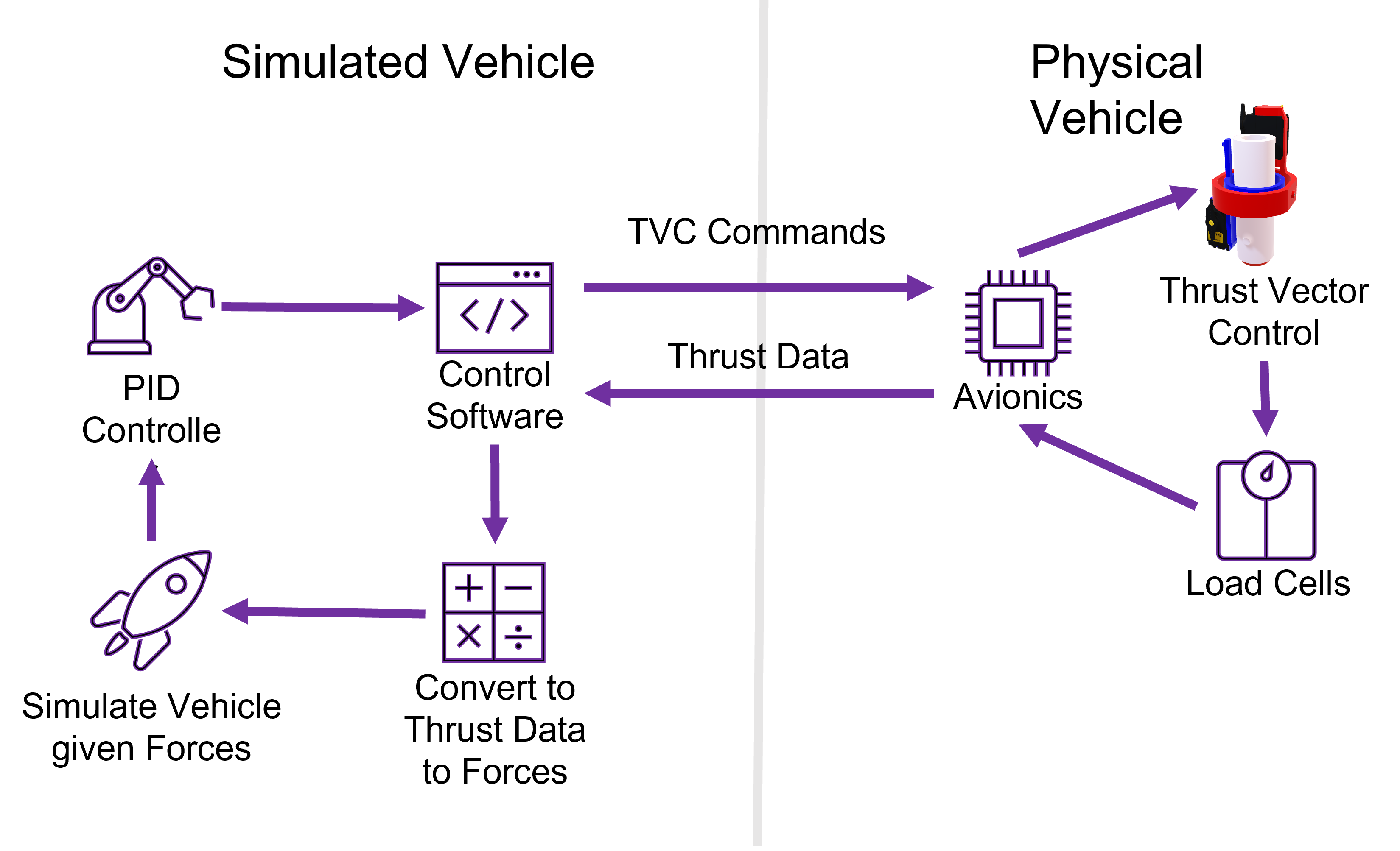
The simulated vehicle comprises a feedback loop where the rocket motor causing forces on load cells translates to forces in the simulation. The control system utilizes a PID which gives commands to the simulated vehicle; the commands are then translated back into hardware as TVC commands. The physical vehicle encompasses the avionics, TVC, and load cells. The physical vehicle receives commands from the simulated vehicle and returns, calculated thrust data back to the control software.
The experimental thrust curve shows that the four load cells managed to match the thrust curve for the Estes F15 within 6.2 Newton Seconds or 13.2% of expected. Due to multiple changes in project and scope LANDER initially chose very cheap load cells since the test stand demonstration was originally mean't to be a verification for much larger goals. Acquiring usable data from the load cells ended up taking much more time and resources than the team initially expected, but thanks to proper risk mitigation the team was able to overcome the challenge and find a real solution.
The Grand Finale
At the conclusion and verification of the Operational Demonstration LANDER has compiled a Final Report for the project. The Final Report compiles two semesters of work into one succinct document that highlights all of the findings from the project.